ECU Power Source Circuit System Voltage Low (B2620A2)
DESCRIPTION
The ECU power source circuit supplies positive (+) voltage to the multiplex tilt and telescopic ECU.
|
DTC No. | Detection Item |
DTC Detection Condition | Trouble Area |
|
B2620A2 | ECU Power Source Circuit System Voltage Low |
The voltage of the ECU power source drops to 8 V or less for 10 seconds or more. |
- ECU-DCC NO. 2 fuse
- Harness or connector
- Multiplex tilt and telescopic ECU
|
WIRING DIAGRAM
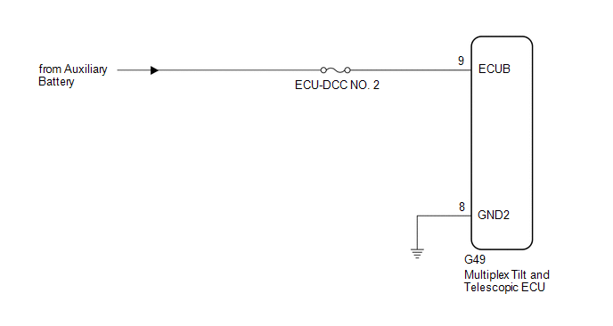
CAUTION / NOTICE / HINT
NOTICE:
Inspect the fuses for circuits related to this system before performing the following procedure.
PROCEDURE
| 1. |
CHECK HARNESS AND CONNECTOR (MULTIPLEX TILT AND TELESCOPIC ECU - AUXILIARY BATTERY) |
| (a) Disconnect the G49 multiplex tilt and telescopic ECU connector. |
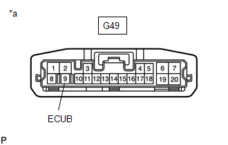 |
|
*a | Front view of wire harness connector
(to Multiplex Tilt and Telescopic ECU) | | |
(b) Measure the voltage according to the value(s) in the table below.
Standard Voltage:
|
Tester Connection | Condition |
Specified Condition |
|
G49-9 (ECUB) - Body ground |
Power switch off | 11 to 14 V |
| NG |
 | REPAIR OR REPLACE HARNESS OR CONNECTOR |
|
OK |
 | |
| 2. |
CHECK HARNESS AND CONNECTOR (MULTIPLEX TILT AND TELESCOPIC ECU - BODY GROUND) |
| (a) Disconnect the G49 multiplex tilt and telescopic ECU connector. |
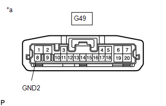 |
|
*a | Front view of wire harness connector
(to Multiplex Tilt and Telescopic ECU) | | |
(b) Measure the resistance according to the value(s) in the table below.
Standard Resistance:
|
Tester Connection | Condition |
Specified Condition |
|
G49-8 (GND2) - Body ground |
Always | Below 1 Ω |
| OK |
 | REPLACE MULTIPLEX TILT AND TELESCOPIC ECU |
| NG |
 | REPAIR OR REPLACE HARNESS OR CONNECTOR |
Tilt Position Sensor or Tilt Motor Circuit Component Internal Failure (B261096)
DESCRIPTION
The tilt motor
(steering column assembly) is operated by the power source voltage
supplied from the multiplex tilt and telescopic ECU and tilts the
steering column up and down. The tilt position sensor (Hall IC) in the
tilt motor (steering column assembly) detects the tilt angle of the
steering column assembly and sends a signal to the multiplex tilt and
telescopic ECU based on that angle.
|
DTC No. | Detection Item |
DTC Detection Condition | Trouble Area |
|
B261096 | Tilt Position Sensor or Tilt Motor Circuit Component Internal Failure |
Tilt operation stops within the operation range while operating. |
- TI&TE Fuse
- Tilt position sensor (steering column assembly)
- Tilt motor (steering column assembly)
- Harness or connector
- Multiplex tilt and telescopic ECU
|
WIRING DIAGRAM

CAUTION / NOTICE / HINT
NOTICE:
Inspect the fuses for circuits related to this system before performing the following inspection procedure.
PROCEDURE
| 1. |
PERFORM ACTIVE TEST USING TECHSTREAM (TILT MOTOR) |
(a) Turn the power switch off.
(b) Connect the Techstream to the DLC3.
(c) Turn the power switch on (IG).
(d) Turn the Techstream on.
(e) Check that the steering wheel tilts up and down.
(f) Enter the following menus: Body Electrical / Tilt & Telescopic / Active Test.
Body Electrical > Tilt&Telescopic > Active Test
|
Tester Display |
| Tilt Motor |
Body Electrical > Tilt&Telescopic > Active Test
|
Tester Display | Measurement Item |
Control Range |
| Tilt Motor |
Tilt operation | UP/DOWN |
OK:
The steering wheel tilts up and down.
| NG |
 | GO TO STEP 6 |
|
OK |
 | |
| 2. |
CHECK HARNESS AND CONNECTOR (MULTIPLEX TILT AND TELESCOPIC ECU - TILT POSITION SENSOR (STEERING COLUMN ASSEMBLY)) |
(a) Disconnect the G49 multiplex tilt and telescopic ECU connector.
(b) Disconnect the G61 tilt motor (steering column assembly) connector.
(c) Measure the resistance according to the value(s) in the table below.
Standard Resistance:
|
Tester Connection | Condition |
Specified Condition |
|
G49-13 (VCI) - G61-4 (VCI) |
Always | Below 1 Ω |
|
G49-16 (TIS) - G61-5 (TIS) |
Always | Below 1 Ω |
|
G49-4 (E1) -G61-6 (E1) |
Always | Below 1 Ω |
|
G49-13 (VCI) or G61-4 (VCI) - Body ground |
Always | 10 kΩ or higher |
|
G49-16 (TIS) or G61-5 (TIS) - Body ground |
Always | 10 kΩ or higher |
|
G49-4 (E1) or G61-6 (E1) - Body ground |
Always | 10 kΩ or higher |
| NG |
 | REPAIR OR REPLACE HARNESS OR CONNECTOR |
|
OK |
 | |
| 3. |
CHECK HARNESS AND CONNECTOR (MULTIPLEX TILT AND TELESCOPIC ECU - BODY GROUND) |
| (a) Disconnect the G49 multiplex tilt and telescopic ECU connector. |
 |
|
*a | Front view of wire harness connector
(to Multiplex Tilt and Telescopic ECU) | | |
(b) Measure the resistance according to the value(s) in the table below.
Standard Resistance:
|
Tester Connection | Condition |
Specified Condition |
|
G49-1 (GND) - Body ground |
Always | Below 1 Ω |
|
G49-8 (GND2) - Body ground |
Always | Below 1 Ω |
| NG |
 | REPAIR OR REPLACE HARNESS OR CONNECTOR |
|
OK |
 | |
| 4. |
CHECK MULTIPLEX TILT AND TELESCOPIC ECU (VCI, TIS TERMINAL VOLTAGE) |
| (a) Reconnect the G49 multiplex tilt and telescopic ECU connector. |
 |
|
*a | Component with harness connected (Multiplex Tilt and Telescopic ECU) | | |
(b) Disconnect the G61 tilt motor (steering column assembly) connector.
(c) Measure the voltage according to the value(s) in the table below.
Standard Voltage:
|
Tester Connection | Condition |
Specified Condition |
|
G49-13 (VCI) - G49-4 (E1) |
Power switch on (IG) |
8 to 14 V |
|
G49-16 (TIS) - G49-4 (E1) |
Power switch on (IG) |
8 to 14 V |
| NG |
 | REPLACE MULTIPLEX TILT AND TELESCOPIC ECU |
|
OK |
 | |
| 5. |
CHECK TILT POSITION SENSOR (STEERING COLUMN ASSEMBLY) |
| (a) Reconnect the G49 multiplex tilt and telescopic ECU connector. |
 |
|
*a | Component with harness connected
(Tilt Motor (Steering Column Assembly)) | | |
(b) Reconnect the G61 tilt motor (steering column assembly) connector.
(c) Measure the voltage according to the value(s) in the table below.
Standard Voltage:
|
Tester Connection | Condition |
Specified Condition |
|
G61-5 (TIS) - G61-6 (E1) |
Steering wheel tilting up or tilting down |
Pulse generation High: 8 to 14 V Low: Below 1 V |
| OK |
 | REPLACE MULTIPLEX TILT AND TELESCOPIC ECU |
| NG |
 | REPLACE STEERING COLUMN ASSEMBLY |
| 6. |
CHECK HARNESS AND CONNECTOR (MULTIPLEX TILT AND TELESCOPIC ECU - AUXILIARY BATTERY) |
| (a) Disconnect the G49 multiplex tilt and telescopic ECU connector. |
 |
|
*a | Front view of wire harness connector
(to Multiplex Tilt and Telescopic ECU) | | |
(b) Measure the voltage according to the value(s) in the table below.
Standard Voltage:
|
Tester Connection | Condition |
Specified Condition |
|
G49-2 (+B) - Body ground |
Always | 11 to 14 V |
| NG |
 | REPAIR OR REPLACE HARNESS OR CONNECTOR |
|
OK |
 | |
| 7. |
CHECK HARNESS AND CONNECTOR (MULTIPLEX TILT AND TELESCOPIC ECU - BODY GROUND) |
| (a) Disconnect the G49 multiplex tilt and telescopic ECU connector. |
 |
|
*a | Front view of wire harness connector
(to Multiplex Tilt and Telescopic ECU) | | |
(b) Measure the resistance according to the value(s) in the table below.
Standard Resistance:
|
Tester Connection | Condition |
Specified Condition |
|
G49-1 (GND) - Body ground |
Always | Below 1 Ω |
|
G49-8 (GND2) - Body ground |
Always | Below 1 Ω |
| NG |
 | REPAIR OR REPLACE HARNESS OR CONNECTOR |
|
OK |
 | |
| 8. |
CHECK HARNESS AND CONNECTOR (MULTIPLEX TILT AND TELESCOPIC ECU - TILT MOTOR (STEERING COLUMN ASSEMBLY)) |
(a) Disconnect the G49 multiplex tilt and telescopic ECU connector.
(b) Disconnect the G61 tilt motor (steering column assembly) connector.
(c) Measure the resistance according to the value(s) in the table below.
Standard Resistance:
|
Tester Connection | Condition |
Specified Condition |
|
G49-7 (TIM+) - G61-1 (TIM+) |
Always | Below 1 Ω |
|
G49-20 (TIM-) - G61-2 (TIM-) |
Always | Below 1 Ω |
|
G49-7 (TIM+) or G61-1 (TIM+) - Body ground |
Always | 10 kΩ or higher |
|
G49-20 (TIM-) or G61-2 (TIM-) - Body ground |
Always | 10 kΩ or higher |
| NG |
 | REPAIR OR REPLACE HARNESS OR CONNECTOR |
|
OK |
 | |
| 9. |
CHECK TILT MOTOR (STEERING COLUMN ASSEMBLY) |
| (a) Disconnect the G61 tilt motor (steering column assembly) connector. |
 |
|
*a | Component without harness connected
(Tilt Motor (Steering Column Assembly)) | | |
(b)
Apply 12 V auxiliary battery voltage to the tilt motor (steering column
assembly) connector. Then check the steering wheel tilt operation.
OK:
|
Measurement Condition | Specified Condition |
- 12 V auxiliary battery positive (+) lead → G61-1 (TIM+)
- 12 V auxiliary battery negative (-) lead → G61-2 (TIM-)
| The steering wheel tilts up. |
- 12 V auxiliary battery positive (+) lead → G61-2 (TIM-)
- 12 V auxiliary battery negative (-) lead → G61-1 (TIM+)
| The steering wheel tilts down. |
| OK |
 | REPLACE MULTIPLEX TILT AND TELESCOPIC ECU |
| NG |
 | REPLACE STEERING COLUMN ASSEMBLY |
Customize Parameters
CUSTOMIZE PARAMETERS
CUSTOMIZE POWER TILT AND POWER TELESCOPIC STEERING COLUMN SYSTEM
HINT:
The following items can be customized.
NOTICE:
- When the customer requests a change in a function, first make sure that the function can be customized.
- Record the current settings before customizing.
(a) Customizing with the Techstream
(1) Connect the Techstream to the DLC3.
(2) Turn the power switch on (IG).
(3) Turn the Techstream on.
(4) Enter the following menus: Body Electrical / Tilt & Telescopic / Utility / Customize.
(5) Select the setting by referring to the table below.
Tilt & Telesco
|
Tester Display | Description |
Default | Setting |
ECU |
| Autoaway/Return Operation Setting |
Turn the auto away/return function |
Tilt ON | $0000:Tilt&Telescopic OFF,$0001:Telescopic ON,$0010:Tilt ON,$0011:Tilt&Telescopic ON |
Multiplex tilt and telescopic ECU |
(b) Customizing with the multi-display
(1) Turn the power switch on (IG).
(2) Select the setting by referring to the table below
(3) Select the following menus: Setup / Vehicle / Vehicle Customization / Other Vehicle Settings.
(4) Select the setting by referring to the table below.
Other Vehicle Settings |
Display | Description |
Default | Setting |
ECU |
| Steering Column Easy-Exit |
Turn the auto away/return function |
Tilt Only | Tilt & Telescopic / Tilt Only / Telescopic Only / Off |
Multiplex tilt and telescopic ECU |
Data List / Active Test
DATA LIST / ACTIVE TEST
READ DATA LIST
HINT:
Using
the Techstream to read the Data List allows the values or states of
switches, sensors, actuators and other items to be read without removing
any parts. This non-intrusive inspection can be very useful because
intermittent conditions or signals may be discovered before parts or
wiring is disturbed. Reading the Data List information early in
troubleshooting is one way to save diagnostic time.
NOTICE:
In
the table below, the values listed under "Normal Condition" are
reference values. Do not depend solely on these reference values when
deciding whether a part is faulty or not.
(a) Turn the power switch off.
(b) Connect the Techstream to the DLC3.
(c) Turn the power switch on (IG).
(d) Turn the Techstream on.
(e) Enter the following menus: Body Electrical / Tilt & Telescopic / Data List.
(f) According to the display on the Techstream, read the Data List.
Body Electrical > Tilt&Telescopic > Data List
|
Tester Display | Measurement Item |
Range | Normal Condition |
Diagnostic Note |
|
Total Distance Traveled |
Driving distance | Min.: 0
Max.: 999999 | - |
- |
| Total Distance Traveled - Unit |
Driving distance unit | km or mile |
- | - |
|
Tilt Up Limit | Uppermost tilt position |
Not Memory or Memory | Not Memory: Position not memorized
Memory: Position memorized |
- |
| Tilt Down Limit |
Lowermost tilt position |
Not Memory or Memory | Not Memory: Position not memorized
Memory: Position memorized |
- |
| Telescopic Short Limit |
Shortest telescopic position |
Not Memory or Memory | Not Memory: Position not memorized
Memory: Position memorized |
- |
| Telescopic Long Limit |
Longest telescopic position |
Not Memory or Memory | Not Memory: Position not memorized
Memory: Position memorized |
- |
| Tilt&Telescopic Memory 1 |
Tilt and telescopic memory position 1 |
Not Memory or Memory | Not Memory: Position not memorized
Memory: Position memorized |
- |
| Tilt&Telescopic Memory 2 |
Tilt and telescopic memory position 2 |
Not Memory or Memory | Not Memory: Position not memorized
Memory: Position memorized |
- |
| Tilt&Telescopic Memory 3 |
Tilt and telescopic memory position 3 |
Not Memory or Memory | Not Memory: Position not memorized
Memory: Position memorized |
- |
| Driver Information Memory 1 |
Driver Information Memory 1 |
Not Memory or Memory |
- | - |
|
Driver Information Memory 2 |
Driver Information Memory 2 |
Not Memory or Memory |
- | - |
|
Driver Information Memory 3 |
Driver Information Memory 3 |
Not Memory or Memory |
- | - |
|
Ignition Switch (CAN) | Communication state of power switch |
OFF or ON | ON: Communication normal
OFF: Communication interrupted |
- |
| Handle Position |
Steering wheel position signal |
Away or Return | Away: Steering wheel in away position
Return: Steering wheel in return position |
- |
| Ignition Switch |
Input state of power switch |
OFF or ON | ON: Input signal normal
OFF: Input signal interrupted |
- |
| Tilt Manual Switch Up |
Input state of tilt up switch |
OFF or ON | - |
- |
| Tilt Manual Switch Down |
Input state of tilt down switch |
OFF or ON | - |
- |
| Telescopic Manual Switch Short |
Input state of telescopic contract switch |
OFF or ON | - |
- |
| Telescopic Manual Switch Long |
Input state of telescopic extend switch |
OFF or ON | - |
- |
| Tilt&Telescopic Manual Switch Voltage |
Voltage data of tilt and telescopic switch |
Min.: 0.000 V Max.: 4.998 V |
Neutral position: Below 0.20 V Tilt up: 1.67 to 2.13 V Tilt down: 0.54 to 0.74 V
Telescopic contract: 1.08 to 1.40 V Telescopic extend: 2.22 to 2.77 V |
- |
| ECU Power Source Voltage |
Voltage data of power supply |
Min.: 0.000 V Max.: 19.992 V |
11.00 to 14.00 V | - |
|
Tilt Position | Current tilt position data |
Min.: 0 Max.: 65535 |
28627 to 36864 | - |
|
Telescopic Position | Current telescopic position data |
Min.: 0 Max.: 65535 |
28627 to 36864 | - |
|
Tilt Return Memory Position |
Memorized tilt return position data |
Min.: 0 Max.: 65535 |
28627 to 36864 | - |
|
Telescopic Return Memory Position |
Memorized telescopic return position data |
Min.: 0 Max.: 65535 |
28627 to 36864 | - |
|
Tilt Up Limit Position |
Uppermost tilt position data |
Min.: 0 Max.: 65535 |
28627 to 36864 | - |
|
Tilt Down Limit Position |
Lowermost tilt position data |
Min.: 0 Max.: 65535 |
28627 to 36864 | - |
|
Telescopic Short Limit Position |
Shortest telescopic position data |
Min.: 0 Max.: 65535 |
28627 to 36864 | - |
|
Telescopic Long Limit Position |
Longest telescopic position data |
Min.: 0 Max.: 65535 |
28627 to 36864 | - |
|
Tilt Memory Position 1 |
Tilt data of memory position 1 |
Min.: 0 Max.: 65535 |
28627 to 36864 | - |
|
Telescopic Memory Position 1 |
Telescopic data of memory position 1 |
Min.: 0 Max.: 65535 |
28627 to 36864 | - |
|
Tilt Memory Position 2 |
Tilt data of memory position 2 |
Min.: 0 Max.: 65535 |
28627 to 36864 | - |
|
Telescopic Memory Position 2 |
Telescopic data of memory position 2 |
Min.: 0 Max.: 65535 |
28627 to 36864 | - |
|
Tilt Memory Position 3 |
Tilt data of memory position 3 |
Min.: 0 Max.: 65535 |
28627 to 36864 | - |
|
Telescopic Memory Position 3 |
Telescopic data of memory position 3 |
Min.: 0 Max.: 65535 |
28627 to 36864 | - |
|
Vehicle Speed | Vehicle speed data |
Min.: 0 km/h (0 mph) Max.: 255 km/h (158 mph) |
Actual vehicle speed |
- |
| Driver Tilt Memory Position 1 |
Driver tilt memory position 1 |
Min.: 0 Max.: 65535 |
28627 to 36864 | - |
|
Driver Telescopic Memory Position 1 |
Driver telescopic memory position 1 |
Min.: 0 Max.: 65535 |
28627 to 36864 | - |
|
Driver Tilt Memory Position 2 |
Driver tilt memory position 2 |
Min.: 0 Max.: 65535 |
28627 to 36864 | - |
|
Driver Telescopic Memory Position 2 |
Driver telescopic memory position 2 |
Min.: 0 Max.: 65535 |
28627 to 36864 | - |
|
Driver Tilt Memory Position 3 |
Driver tilt memory position 3 |
Min.: 0 Max.: 65535 |
28627 to 36864 | - |
|
Driver Telescopic Memory Position 3 |
Driver telescopic memory position 3 |
Min.: 0 Max.: 65535 |
28627 to 36864 | - |
|
Tilt Motor Machine Lock Memory Data |
Tilt Motor Machine Lock Memory Data |
Not Exist or Existed |
- | - |
|
Telescopic Motor Machine Lock Memory Data |
Telescopic Motor Machine Lock Memory Data |
Not Exist or Existed |
- | - |
|
Autoaway/Return Operation Setting |
Autoaway/Return Operation Setting |
Tilt&Telescopic OFF, Telescopic ON, Tilt ON or Tilt&Telescopic ON |
Tilt&Telescopic OFF: Tilt and telescopic operations prohibited
Telescopic ON: Only telescopic operations permitted Tilt ON: Only tilt operations permitted
Tilt&Telescopic ON: Tilt and telescopic operations permitted |
- |
ACTIVE TEST
HINT:
Using
the Techstream to perform Active Tests allows relays, VSVs, actuators
and other items to be operated without removing any parts. This
non-intrusive functional inspection can be very useful because
intermittent operation may be discovered before parts or wiring is
disturbed. Performing Active Tests early in troubleshooting is one way
to save diagnostic time. Data List information can be displayed while
performing Active Tests.
(a) Turn the power switch off.
(b) Connect the Techstream to the DLC3.
(c) Turn the power switch on (IG).
(d) Turn the Techstream on.
(e) Enter the following menus: Body Electrical / Tilt & Telescopic / Active Test.
(f) According to the display on the Techstream, perform the Active Test.
Body Electrical > Tilt&Telescopic > Active Test
|
Tester Display | Measurement Item |
Control Range |
| Tilt Motor |
Tilt operation | UP/DOWN |
|
Telescopic Motor | Telescopic operation |
LONG/SHORT |
Diagnosis System
DIAGNOSIS SYSTEM
DESCRIPTION
(a)
When troubleshooting a vehicle with the diagnostic system, the only
difference from the usual troubleshooting procedure is connecting the
Techstream to the vehicle and reading various data output from the
multiplex tilt and telescopic ECU.
The multiplex tilt and telescopic ECU stores DTCs when the ECU detects a malfunction in itself or in its circuits.
To
check the DTCs, connect the Techstream to the DLC3 on the vehicle. The
Techstream enables the DTCs to be cleared, several actuators to be
activated, and the freeze frame data and various forms of steering data
to be checked.
CHECK DLC3
(a) Check the DLC3.
Click here

Diagnostic Trouble Code Chart
DIAGNOSTIC TROUBLE CODE CHART
Power Tilt and Power Telescopic Steering Column System |
DTC No. | Detection Item |
DTC Detection Condition | Link |
|
B26031C | Tilt and Telescopic Manual Switch Circuit Circuit Voltage Out of Range |
When operating the tilt and telescopic switch, an abnormal voltage value is sent to the multiplex tilt and telescopic ECU. |
 |
|
B261096 | Tilt Position Sensor or Tilt Motor Circuit Component Internal Failure |
Tilt operation stops within the operation range while operating. |
 |
|
B261196 | Telescopic Position Sensor or Telescopic Motor Circuit Component Internal Failure |
Telescopic operation stops within the operation range while operating. |
 |
|
B2620A2 | ECU Power Source Circuit System Voltage Low |
The voltage of the ECU power source drops to 8 V or less for 10 seconds or more. |
 |
|
U014287 | Lost Communication with Body Control Module "B" Missing Message |
One of the following conditions is met:
- Signals (memory-related data) from the main body ECU (multiplex network body ECU) are interrupted for 3.3 seconds.
- Signals (IG switch signals) from the main body ECU (multiplex network body ECU) are interrupted for 10 seconds or more.
|
 |
|
U015587 | Lost Communication with Instrument Panel Cluster (IPC) Control Module Missing Message |
Signals from the combination meter assembly are interrupted for 10 seconds or more. |
 |
|
U020887 | Lost Communication with "Seat Control Module A" Missing Message |
Signals
(memory or recall request signal) received from the position control
ECU assembly (driver seat) are interrupted for 10 seconds or more. |
 |
Dtc Check / Clear
DTC CHECK / CLEAR
CHECK DTC
(a) Turn the power switch off.
(b) Connect the Techstream to the DLC3.
(c) Turn the power switch on (IG).
(d) Turn the Techstream on.
(e) Enter the following menus: Body Electrical / Tilt & Telescopic / Trouble Codes.
Body Electrical > Tilt&Telescopic > Trouble Codes
(f) Read the DTCs.
Click here 
CLEAR DTC
(a) Turn the power switch off.
(b) Connect the Techstream to the DLC3.
(c) Turn the power switch on (IG).
(d) Turn the Techstream on.
(e) Enter the following menus: Body Electrical / Tilt & Telescopic / Trouble Codes.
Body Electrical > Tilt&Telescopic > Clear DTCs
(f) Clear the DTCs.
Fail-safe Chart
FAIL-SAFE CHART
HINT:
If
the power source voltage to the multiplex tilt and telescopic ECU
returns to normal within 10 seconds during tilt or telescopic operation,
the operation will be resumed. If it returns to normal after 10 seconds
have elapsed, the operation restarts when a tilt or telescopic
operation signal is sent to the multiplex tilt and telescopic ECU again.
Fail-safe Operation |
DTC Code | Detection Item |
Fail-safe Operation |
|
B26031C | Tilt and Telescopic Manual Switch Circuit Circuit Voltage Out of Range |
The tilt and telescopic operation using the switch is suspended. |
|
B261096 | Tilt Position Sensor or Tilt Motor Circuit Component Internal Failure |
The tilt operation is suspended. |
|
B261196 | Telescopic Position Sensor or Telescopic Motor Circuit Component Internal Failure |
The telescopic operation is suspended. |
|
B2620A2 | ECU Power Source Circuit System Voltage Low |
The tilt and telescopic operation is suspended. |
|
U014287 | Lost Communication with Body Control Module "B" Missing Message |
The
tilt and telescopic operation is limited depending on which ECU has
lost communication. For details, refer to Fail-safe Function. |
|
U015587 | Lost Communication with Instrument Panel Cluster (IPC) Control Module Missing Message |
|
U020887 | Lost Communication with "Seat Control Module A" Missing Message |
FAIL-SAFE FUNCTION
(a)
If a malfunction in the tilt position sensor signal or telescopic
position sensor signal occurs while operating the power tilt or power
telescopic function, the multiplex tilt and telescopic ECU stops the
operation of the power tilt and power telescopic steering column system.
(b)
If the power source voltage to the ECU drops below approximately 8 V
while operating the power tilt or power telescopic function, the ECU
stops the operation of the power tilt and power telescopic steering
column system.
(c) If the ECU detects that the
motor has locked during the operation of the power tilt or power
telescopic function, the ECU stops the operation of the power tilt and
power telescopic steering column system.
(d) If the
communication of an ECU that is related to the power tilt and power
telescopic steering column system is interrupted, the control of
functions of the multiplex tilt and telescopic ECU are limited as shown
in the table below.
|
Tilt and Telescopic Operation |
Main Body ECU (Multiplex Network Body ECU) Communication Interruption |
Combination Meter Assembly Communication Interruption |
Position Control ECU Assembly (Driver Seat) Communication Interruption |
All ECUs*1 Communication Interruption |
|
Manual | â—‹*2 |
â—‹ | â—‹ |
â—‹*2 |
| Auto away/return |
X | X |
â—‹ | X |
|
Position memory (Memorization) |
X | â—‹ |
â—‹ | X |
|
Position memory (Recall) |
X | X |
X | X |
HINT:
- â—‹: Operates
X: Does not operate
- *1: All ECUs that are related to the power tilt and power telescopic steering column system.
- *2: The operation is permitted if the power switch is on (IG) while the
signal from the main body ECU (multiplex network body ECU) is
interrupted. The operation is prohibited if the power switch is off
while the signal from the main body ECU (multiplex network body ECU) is
interrupted.
Freeze Frame Data
FREEZE FRAME DATA
FREEZE FRAME DATA
NOTICE:
- Freeze frame data values will vary depending on the measurement
conditions, surroundings, or vehicle conditions. For this reason, there
may be a problem even when the values are within specifications.
- Turn the power switch on (IG) and park the vehicle on level ground. Check the freeze frame data by using the Techstream.
(a) Turn the power switch off.
(b) Connect the Techstream to the DLC3.
(c) Turn the power switch on (IG).
(d) Turn the Techstream on.
(e) Check the freeze frame data.
(f) Enter the following menus: Body Electrical / Tilt & Telescopic / Trouble Codes.
Body Electrical > Tilt&Telescopic > Trouble Codes Body Electrical > Tilt&Telescopic
|
Tester Display | Measurement Item |
Range | Normal Condition |
Diagnostic Note |
|
Total Distance Traveled |
Driving distance | Min.: 0
Max.: 999999 | - |
- |
| Total Distance Traveled - Unit |
Driving distance unit | km or mile |
- | - |
|
Tilt Up Limit | Uppermost tilt position |
Not Memory or Memory | Not Memory: Position not memorized
Memory: Position memorized |
- |
| Tilt Down Limit |
Uppermost tilt position |
Not Memory or Memory | Not Memory: Position not memorized
Memory: Position memorized |
- |
| Telescopic Short Limit |
Shortest telescopic position |
Not Memory or Memory | Not Memory: Position not memorized
Memory: Position memorized |
- |
| Telescopic Long Limit |
Longest telescopic position |
Not Memory or Memory | Not Memory: Position not memorized
Memory: Position memorized |
- |
| Tilt&Telescopic Memory 1 |
Tilt and telescopic memory position 1 |
Not Memory or Memory | Not Memory: Position not memorized
Memory: Position memorized |
- |
| Tilt&Telescopic Memory 2 |
Tilt and telescopic memory position 2 |
Not Memory or Memory | Not Memory: Position not memorized
Memory: Position memorized |
- |
| Tilt&Telescopic Memory 3 |
Tilt and telescopic memory position 3 |
Not Memory or Memory | Not Memory: Position not memorized
Memory: Position memorized |
- |
| Driver Information Memory 1 |
Driver Information Memory 1 |
Not Memory or Memory |
- | - |
|
Driver Information Memory 2 |
Driver Information Memory 2 |
Not Memory or Memory |
- | - |
|
Driver Information Memory 3 |
Driver Information Memory 3 |
Not Memory or Memory |
- | - |
|
Ignition Switch (CAN) | Communication state of power switch |
OFF or ON | ON: Communication normal
OFF: Communication interrupted |
- |
| Handle Position |
Steering wheel position signal |
Away or Return | Away: Steering wheel in away position
Return: Steering wheel in return position |
- |
| Ignition Switch |
Input state of power switch |
OFF or ON | ON: Input signal normal
OFF: Input signal interrupted |
- |
| Tilt Manual Switch Up |
Input state of tilt up switch |
OFF or ON | - |
- |
| Tilt Manual Switch Down |
Input state of tilt down switch |
OFF or ON | - |
- |
| Telescopic Manual Switch Short |
Input state of telescopic contract switch |
OFF or ON | - |
- |
| Telescopic Manual Switch Long |
Input state of telescopic extend switch |
OFF or ON | - |
- |
| Tilt&Telescopic Manual Switch Voltage |
Voltage data of tilt and telescopic switch |
Min.: 0.000 V Max.: 4.998 V |
Neutral position: Below 0.20 V Tilt up: 1.67 to 2.13 V Tilt down: 0.54 to 0.74 V
Telescopic contract: 1.08 to 1.40 V Telescopic extend: 2.22 to 2.77 V |
- |
| ECU Power Source Voltage |
Voltage data of power supply |
Min.: 0.000 V Max.: 19.992 V |
11.00 to 14.00 V | - |
|
Tilt Position | Current tilt position data |
Min.: 0 Max.: 65535 |
28627 to 36864 | - |
|
Telescopic Position | Current telescopic position data |
Min.: 0 Max.: 65535 |
28627 to 36864 | - |
|
Tilt Return Memory Position |
Memorized tilt return position data |
Min.: 0 Max.: 65535 |
28627 to 36864 | - |
|
Telescopic Return Memory Position |
Memorized telescopic return position data |
Min.: 0 Max.: 65535 |
28627 to 36864 | - |
|
Tilt Up Limit Position |
Uppermost tilt position data |
Min.: 0 Max.: 65535 |
28627 to 36864 | - |
|
Tilt Down Limit Position |
Lowermost tilt position data |
Min.: 0 Max.: 65535 |
28627 to 36864 | - |
|
Telescopic Short Limit Position |
Shortest telescopic position data |
Min.: 0 Max.: 65535 |
28627 to 36864 | - |
|
Telescopic Long Limit Position |
Longest telescopic position data |
Min.: 0 Max.: 65535 |
28627 to 36864 | - |
|
Tilt Memory Position 1 |
Tilt data of memory position 1 |
Min.: 0 Max.: 65535 |
28627 to 36864 | - |
|
Telescopic Memory Position 1 |
Telescopic data of memory position 1 |
Min.: 0 Max.: 65535 |
28627 to 36864 | - |
|
Tilt Memory Position 2 |
Tilt data of memory position 2 |
Min.: 0 Max.: 65535 |
28627 to 36864 | - |
|
Telescopic Memory Position 2 |
Telescopic data of memory position 2 |
Min.: 0 Max.: 65535 |
28627 to 36864 | - |
|
Tilt Memory Position 3 |
Tilt data of memory position 3 |
Min.: 0 Max.: 65535 |
28627 to 36864 | - |
|
Telescopic Memory Position 3 |
Telescopic data of memory position 3 |
Min.: 0 Max.: 65535 |
28627 to 36864 | - |
|
Vehicle Speed | Vehicle speed data |
Min.: 0 km/h (0 mph) Max.: 255 km/h (158 mph) |
Actual vehicle speed |
- |
| Driver Tilt Memory Position 1 |
Driver tilt memory position 1 |
Min.: 0 Max.: 65535 |
28627 to 36864 | - |
|
Driver Telescopic Memory Position 1 |
Driver telescopic memory position 1 |
Min.: 0 Max.: 65535 |
28627 to 36864 | - |
|
Driver Tilt Memory Position 2 |
Driver tilt memory position 2 |
Min.: 0 Max.: 65535 |
28627 to 36864 | - |
|
Driver Telescopic Memory Position 2 |
Driver telescopic memory position 2 |
Min.: 0 Max.: 65535 |
28627 to 36864 | - |
|
Driver Tilt Memory Position 3 |
Driver tilt memory position 3 |
Min.: 0 Max.: 65535 |
28627 to 36864 | - |
|
Driver Telescopic Memory Position 3 |
Driver telescopic memory position 3 |
Min.: 0 Max.: 65535 |
28627 to 36864 | - |
|
Tilt Motor Machine Lock Memory Data |
Tilt Motor Machine Lock Memory Data |
Not Exist or Existed |
- | - |
|
Telescopic Motor Machine Lock Memory Data |
Telescopic Motor Machine Lock Memory Data |
Not Exist or Existed |
- | - |
|
Autoaway/Return Operation Setting |
Autoaway/Return Operation Setting |
Tilt&Telescopic OFF, Telescopic ON, Tilt ON or Tilt&Telescopic ON |
Tilt&Telescopic OFF: Tilt and telescopic operations prohibited
Telescopic ON: Only telescopic operations permitted Tilt ON: Only tilt operations permitted
Tilt&Telescopic ON: Tilt and telescopic operations permitted |
- |
How To Proceed With Troubleshooting
CAUTION / NOTICE / HINT
HINT:
*: Use the Techstream.
PROCEDURE
| 1. |
VEHICLE BROUGHT TO WORKSHOP |
|
NEXT |
 | |
| 2. |
INSPECT AUXILIARY BATTERY VOLTAGE |
Standard Voltage:
11 to 14 V (Power switch off)
If the voltage is below 11 V, recharge or replace the auxiliary battery before proceeding.
|
NEXT |
 | |
| 3. |
CHECK CAN COMMUNICATION SYSTEM* |
(a) Use the Techstream to check if the CAN communication system is functioning normally.
Click here 
| Result |
Proceed to |
| CAN DTCs are not output. |
A |
| CAN DTCs are output. |
B |
| B |
 | GO TO CAN COMMUNICATION SYSTEM |
|
A |
 | |
(a) Check for DTCs.
Body Electrical > Tilt&Telescopic > Trouble Codes
| Result |
Proceed to |
| DTCs are not output. |
A |
| DTCs are output. |
B |
| B |
 | GO TO DIAGNOSTIC TROUBLE CODE CHART |
|
A |
 | |
| 5. |
PROBLEM SYMPTOMS TABLE |
(a) Refer to Problem Symptoms Table.
Click here 
| Result |
Proceed to |
| Problem symptom does not occur. |
A |
| Problem symptom occurs. |
B |
| B |
 | GO TO STEP 7 |
|
A |
 | |
| 6. |
OVERALL ANALYSIS AND TROUBLESHOOTING* |
(a) Terminals of ECU.
Click here 
(b) Data List / Active Test.
Click here

|
NEXT |
 | |
|
NEXT |
 | |
| NEXT |
 | END |
IG Power Source Circuit
DESCRIPTION
When the power
switch is turned on (IG), the IG power source circuit supplies positive
(+) voltage to the multiplex tilt and telescopic ECU.
WIRING DIAGRAM
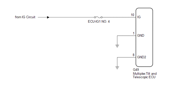
CAUTION / NOTICE / HINT
NOTICE:
Inspect the fuses for circuits related to this system before performing the following procedure.
PROCEDURE
| 1. |
CHECK HARNESS AND CONNECTOR (MULTIPLEX TILT AND TELESCOPIC ECU - AUXILIARY BATTERY) |
| (a) Disconnect the G49 multiplex tilt and telescopic ECU connector. |
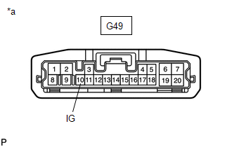 |
|
*a | Front view of wire harness connector
(to Multiplex Tilt and Telescopic ECU) | | |
(b) Measure the voltage according to the value(s) in the table below.
Standard Voltage:
|
Tester Connection | Condition |
Specified Condition |
|
G49-10 (IG) - Body ground |
Power switch on (IG) |
11 to 14 V |
| NG |
 | REPAIR OR REPLACE HARNESS OR CONNECTOR |
|
OK |
 | |
| 2. |
CHECK HARNESS AND CONNECTOR (MULTIPLEX TILT AND TELESCOPIC ECU - BODY GROUND) |
| (a) Disconnect the G49 multiplex tilt and telescopic ECU connector. |
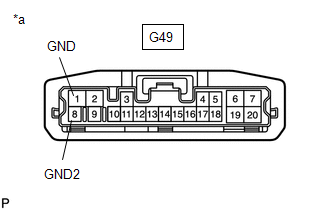 |
|
*a | Front view of wire harness connector
(to Multiplex Tilt and Telescopic ECU) | | |
(b) Measure the resistance according to the value(s) in the table below.
Standard Resistance:
|
Tester Connection | Condition |
Specified Condition |
|
G49-1 (GND) - Body ground |
Always | Below 1 Ω |
|
G49-8 (GND2) - Body ground |
Always | Below 1 Ω |
| OK |
 | REPLACE MULTIPLEX TILT AND TELESCOPIC ECU |
| NG |
 | REPAIR OR REPLACE HARNESS OR CONNECTOR |
Parts Location
PARTS LOCATION
ILLUSTRATION
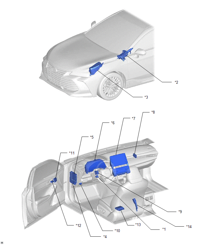
|
*1 | TILT AND TELESCOPIC SWITCH |
*2 | STEERING COLUMN ASSEMBLY |
|
*3 | NO. 1 ENGINE ROOM RELAY BLOCK AND NO. 1 JUNCTION BLOCK ASSEMBLY
- TI&TE FUSE | *4 |
INSTRUMENT PANEL JUNCTION BLOCK ASSEMBLY - ECU-DCC NO. 2 FUSE
- ECU-IG1 NO. 4 FUSE |
|
*5 | MAIN BODY ECU (MULTIPLEX NETWORK BODY ECU) |
*6 | COMBINATION METER ASSEMBLY |
|
*7 | RADIO AND DISPLAY RECEIVER ASSEMBLY |
*8 | NETWORK GATEWAY ECU |
|
*9 | MULTIPLEX TILT AND TELESCOPIC ECU |
*10 | DLC3 |
|
*11 | OUTER MIRROR CONTROL ECU ASSEMBLY (Driver Door) |
*12 | SEAT MEMORY SWITCH |
|
*13 | POSITION CONTROL ECU ASSEMBLY (Driver Seat) |
*14 | FRONT SEAT INNER BELT ASSEMBLY (Driver Seat) |
Precaution
PRECAUTION
PRECAUTION FOR DISCONNECTING CABLE FROM NEGATIVE AUXILIARY BATTERY TERMINAL
NOTICE:
When
disconnecting the cable from the negative (-) auxiliary battery
terminal, initialize the following system(s) after the cable is
reconnected:
|
System | See Procedure |
|
Lane Departure Alert System (w/ Steering Control) |
 |
|
Intelligent Clearance Sonar System |
|
Parking Assist Monitor System |
|
Panoramic View Monitor System |
|
Pre-collision System |
|
Lighting System (for HV Model with Cornering Light) |
HANDLING PRECAUTIONS
(a) When handling electronic parts:
(1)
Avoid any impact to electronic parts such as ECUs and relays. Replace
these parts with new ones if dropped or subjected to a severe blow.
(2) Do not expose any electronic parts to high temperatures or humidity.
(3) Do not touch the connector terminals in order to prevent deformation or malfunctions due to static electricity.
NOTICE:
This
vehicle is equipped with a Supplemental Restraint System (SRS). Failure
to carry out service operations in the correct sequence could cause the
SRS to unexpectedly deploy during servicing. This may cause a serious
accident.
Before servicing (including inspection,
replacement, removal and installation of parts), be sure to read the
precautionary notices for Supplemental Restraint System.
Click here

HANDLING PRECAUTIONS FOR SRS AIRBAG SYSTEM
Problem Symptoms Table
PROBLEM SYMPTOMS TABLE
HINT:
- Use the table below to help determine the cause of problem symptoms. If
multiple suspected areas are listed, the potential causes of the
symptoms are listed in order of probability in the "Suspected Area"
column of the table.
- Check each system by checking the suspected areas in the order they are listed. Replace parts as necessary.
- Inspect the fuses and relays related to this system before inspecting the suspected area below.
Power Tilt and Power Telescopic Steering Column System |
Symptom | Suspected Area |
Link |
| Only manual switch does not operate |
Tilt and telescopic manual switch circuit |
 |
|
Only auto away/return function does not operate |
Check customize status of auto away/return function using the Techstream |
 |
|
IG power source circuit |
 |
|
Only auto away function does not operate |
Smart key system (for start function) |
 |
|
Multiplex tilt and telescopic ECU |
 |
|
Only auto return function does not operate |
Smart key system (for start function) |
 |
|
Multiplex tilt and telescopic ECU |
 |
|
Only microcomputer preset memory/recall function does not operate with the set switch operation |
Front power seat control system (w/ Memory) |
 |
|
Seat memory switch |
 |
|
Position control ECU assembly (Driver Seat) |
 |
|
Multiplex tilt and telescopic ECU |
 |
System Description
SYSTEM DESCRIPTION
FUNCTION OF MAIN COMPONENTS
|
Component | Function |
|
Multiplex tilt and telescopic ECU | This
ECU sends a control signal to the tilt motor (steering column assembly)
and telescopic motor (steering column assembly), based on signals from
each switch, to adjust the steering position. |
|
Tilt motor (steering column assembly) | This motor is activated by a signal from the multiplex tilt and telescopic ECU and adjusts the tilt position.
The tilt position sensor in the motor detects the tilt position by counting the number of pulses as the motor rotates. |
|
Telescopic motor (steering column assembly) | This motor is activated by a signal from the multiplex tilt and telescopic ECU and adjusts the telescopic position.
The
telescopic position sensor in the motor detects the telescopic position
by counting the number of pulses as the motor rotates. |
MANUAL OPERATION
(a) The tilt and telescopic positions can be adjusted as desired by operating the tilt and telescopic switch.
AUTO AWAY/RETURN FUNCTION
(a)
When the power source mode is changed from on (ACC) or on (IG) to off,
and the multiplex tilt and telescopic ECU receives a seat belt release
signal, the steering wheel automatically tilts up and fully retracts.
HINT:
The
default setting for the telescopic system of the auto away/return
function is off. Whether or not the telescopic system of the auto
away/return function operates can be set using customize settings.
(b)
When the power source mode is changed from off to on (ACC) or on (IG),
or the multiplex tilt and telescopic ECU receives a seat belt fastened
signal, the steering wheel automatically returns to the previous
position which was set before the power source was turned off.
(c) The auto away/return function can be prohibited by using the Techstream.
Click here 
DRIVING POSITION MEMORY FUNCTION
(a)
The system can memorize/recall two driving positions by operating the
seat memory switch. Even if these positions are changed when a driver is
getting in/out, it can recall the memory position by one-touch
operation if the steering wheel column position, seat position and outer
mirror surface position of the driver are stored.
System Diagram
SYSTEM DIAGRAM
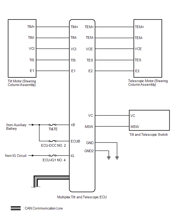
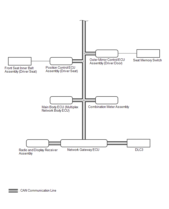 Communication Table
 |
Transmitting ECU (Transmitter) |
Receiving ECU | Signal |
Communication Method |
| Main Body ECU (Multiplex Network Body ECU) |
Multiplex Tilt and Telescopic ECU |
- IG SW signal
- Store command of driver seat memory
- Recall command of driver seat memory
- Auto away/return state signal
| CAN |
|
Position Control ECU Assembly (Driver Seat) |
Multiplex Tilt and Telescopic ECU |
- Memory recall signal
- Start signal to play tilt and telescopic steering
- Stop signal to play memory
|
| Combination Meter Assembly |
Multiplex Tilt and Telescopic ECU | Vehicle speed signal |
|
Multiplex Tilt and Telescopic ECU | Main Body ECU (Multiplex Network Body ECU) |
State signal of tilt and telescopic steering |
|
Multiplex Tilt and Telescopic ECU |
Position Control ECU Assembly (Driver Seat) |
- Tilt and telescopic recall and execution signal
- Tilt and telescopic recall and end signal
|
| Tilt and Telescopic Switch |
Multiplex Tilt and Telescopic ECU |
Tilt and Telescopic Switch signal |
Direct line |
Terminals Of Ecu
TERMINALS OF ECU
MULTIPLEX TILT AND TELESCOPIC ECU

|
*a | Component with harness connected
(Multiplex Tilt and Telescopic ECU) |
- | - |
(a) Measure the voltage and resistance according to the value(s) in the table below.
HINT:
Inspect the connectors from the back side while the connectors are connected.
|
Terminal No. (Symbol) | Wiring Color |
Terminal Description | Condition |
Specified Condition |
|
G49-1 (GND) - Body ground |
W-B - Body ground | ECU ground |
Always | Below 1 Ω |
|
G49-2 (+B) - G49-1 (GND) |
B - W-B | Motor power source |
Always | 11 to 14 V |
|
G49-3 (CANP) - G49-11 (CANN) |
R - W | CAN communication |
Power switch off | 54 to 69 Ω |
|
G49-4 (E1) - Body ground |
BE - Body ground | Tilt sensor ground |
Always | Below 1 Ω |
|
G49-5 (VC) - G49-18 (MSW) |
L - GR | Tilt and telescopic switch signal |
Power switch on (IG) |
4.9 to 5.1 V |
|
G49-6 (TEM+) - G49-1 (GND) |
LA-B - W-B |
Telescopic motor output |
- Power switch on (IG)
- Steering column contracting
| 11 to 14 V |
|
Telescopic motor not operating |
Below 1 V |
|
G49-7 (TIM+) - G49-1 (GND) |
LA-LG - W-B |
Tilt motor output |
- Power switch on (IG)
- Steering wheel tilting up
| 11 to 14 V |
|
Tilt motor not operating |
Below 1 V |
|
G49-8 (GND2) - Body ground |
W-B - Body ground | ECU ground |
Always | Below 1 Ω |
|
G49-9 (ECUB) - G49-1 (GND) |
G - W-B | ECU power source |
Always | 11 to 14 V |
|
G49-10 (IG) - G49-1 (GND) |
L - W-B | IG signal / IG power source |
Power switch on (IG) |
11 to 14 V |
|
Power switch off | Below 1 V |
|
G49-13 (VCI) - G49-4 (E1) |
B - BE | Tilt sensor power source |
Power switch on (IG) |
8 to 14 V |
|
G49-14 (VCE) - G49-17 (E2) |
GR - LG | Telescopic sensor power source |
Power switch on (IG) |
8 to 14 V |
|
G49-15 (TES) - G49-17 (E2) |
R - LG | Telescopic sensor signal |
Telescopic motor operating |
Pulse generation HI: 8 to 14 V LOW: Below 1 V |
|
G49-16 (TIS) - G49-4 (E1) |
W - BE | Tilt sensor signal |
Tilt motor operating |
Pulse generation HI: 8 to 14 V LOW: Below 1 V |
|
G49-17 (E2) - Body ground |
LG - Body ground | Telescopic sensor ground |
Always | Below 1 Ω |
|
G49-19 (TEM-) - G49-1 (GND) |
LA-G - W-B |
Telescopic motor output |
- Power switch on (IG)
- Steering column extending
| 11 to 14 V |
|
Telescopic motor not operating |
Below 1 V |
|
G49-20 (TIM-) - G49-1 (GND) |
LA-L - W-B |
Tilt motor output |
- Power switch on (IG)
- Steering wheel tilting down
| 11 to 14 V |
|
Tilt motor not operating |
Below 1 V |
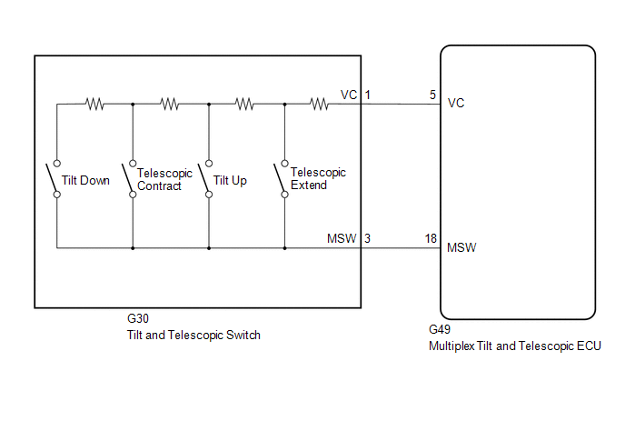
Tilt and Telescopic Manual Switch Circuit
DESCRIPTION
Different
voltage values are sent to the multiplex tilt and telescopic ECU by
operating the tilt and telescopic switch. The multiplex tilt and
telescopic ECU then judges which motor and in which direction that motor
should operate based on the voltage value.
WIRING DIAGRAM
PROCEDURE
| 1. |
READ VALUE USING TECHSTREAM (TILT MANUAL SWITCH UP/DOWN, TELESCOPIC MANUAL SWITCH SHORT/LONG) |
(a) Turn the power switch off.
(b) Connect the Techstream to the DLC3.
(c) Turn the power switch on (IG).
(d) Turn the Techstream on.
(e) Read the Data List according to the display on the Techstream.
Body Electrical > Tilt&Telescopic > Data List
|
Tester Display |
| Tilt Manual Switch Up |
|
Tilt Manual Switch Down |
|
Telescopic Manual Switch Short |
|
Telescopic Manual Switch Long |
Body Electrical > Tilt&Telescopic > Data List
|
Tester Display | Measurement Item |
Range | Normal Condition |
Diagnostic Note |
|
Tilt Manual Switch Up | Input state of tilt up switch |
OFF or ON | - |
- |
| Tilt Manual Switch Down |
Input state of tilt down switch |
OFF or ON | - |
- |
| Telescopic Manual Switch Short |
Input state of telescopic contract switch |
OFF or ON | - |
- |
| Telescopic Manual Switch Long |
Input state of telescopic extend switch |
OFF or ON | - |
- |
OK:
The value of each Data List item changes in accordance with the operation of the switch.
| OK |
 | REPLACE MULTIPLEX TILT AND TELESCOPIC ECU |
|
NG |
 | |
| 2. |
CHECK HARNESS AND CONNECTOR (MULTIPLEX TILT AND TELESCOPIC ECU - TILT AND TELESCOPIC SWITCH) |
(a) Disconnect the G49 multiplex tilt and telescopic ECU connector.
(b) Disconnect the G30 tilt and telescopic switch connector.
(c) Measure the resistance according to the value(s) in the table below.
Standard Resistance:
|
Tester Connection | Condition |
Specified Condition |
|
G49-5 (VC) - G30-1 (VC) |
Always | Below 1 Ω |
|
G49-18 (MSW) - G30-3 (MSW) |
Always | Below 1 Ω |
|
G49-5 (VC) or G30-1 (VC) - Body ground |
Always | 10 kΩ or higher |
|
G49-18 (MSW) or G30-3 (MSW) - Body ground |
Always | 10 kΩ or higher |
| NG |
 | REPAIR OR REPLACE HARNESS OR CONNECTOR |
|
OK |
 | |
| 3. |
CHECK MULTIPLEX TILT AND TELESCOPIC ECU (VC TERMINAL VOLTAGE) |
| (a) Reconnect the G49 multiplex tilt and telescopic ECU connector. |
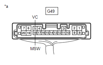 |
|
*a | Component with harness connected
(Multiplex Tilt and Telescopic ECU) | | |
(b) Measure the voltage according to the value(s) in the table below.
Standard Voltage:
|
Tester Connection | Condition |
Specified Condition |
|
G49-5 (VC) - G49-18 (MSW) |
Power switch on (IG) |
4.9 to 5.1 V |
| NG |
 | REPLACE MULTIPLEX TILT AND TELESCOPIC ECU |
|
OK |
 | |
| 4. |
CHECK TILT AND TELESCOPIC SWITCH |
| (a) Remove the tilt and telescopic switch. Click here
 |
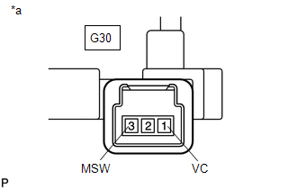 |
|
*a | Component without harness connected
(Tilt and Telescopic Switch) | | |
(b) Measure the resistance according to the value(s) in the table below.
Standard Resistance:
|
Tester Connection | Condition |
Specified Condition |
|
G30-1 (VC) - G30-3 (MSW) |
Tilt up | 342 to 378 Ω |
|
Tilt down | 1890.5 to 2089.5 Ω |
|
Telescopic contract | 750.5 to 829.5 Ω |
|
Telescopic extend | 152 to 168 Ω |
| OK |
 | REPLACE MULTIPLEX TILT AND TELESCOPIC ECU |
| NG |
 | REPLACE TILT AND TELESCOPIC SWITCH |


 Communication Table


