Components
COMPONENTS
ILLUSTRATION
|
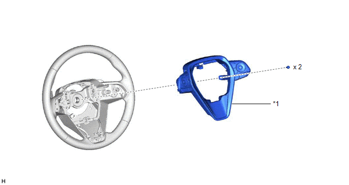
*1 | STEERING PAD SWITCH ASSEMBLY |
- | - |
Inspection
INSPECTION
PROCEDURE
1. INSPECT STEERING PAD SWITCH ASSEMBLY
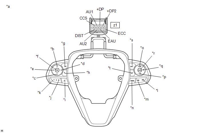
(a) Measure the resistance according to the value(s) in the table below.
|
*a | Component without harness connected
(Steering Pad Switch Assembly) |
*b | Up |
|
*c | Down |
*d | Right |
|
*e | Left |
*f | OK |
|
*g | Back |
*h | On/off Hook |
|
*i | Voice |
*j | Volume+ |
|
*k | Volume- |
*l | Seek+ |
|
*m | Seek- |
*n | MODE |
|
*o | +RES |
*p | -SET |
|
*q | Cruise Control Main |
*r | CANCEL |
|
*s | Distance Control |
*t | Lane Departure Alert |
Standard Resistance:
|
Tester Connection | Condition |
Specified Condition |
|
z1-3 (AU1) - z1-10 (EAU) |
No switch pushed | 95 to 105 kΩ |
|
Seek+ switch pushed | Below 2.5 Ω |
|
Seek- switch pushed | 313 to 345 Ω |
|
Volume+ switch pushed |
950 to 1050 Ω |
|
Volume- switch pushed |
2955 to 3265 Ω |
|
z1-9 (AU2) - z1-10 (EAU) |
No switch pushed | 95 to 105 kΩ |
|
MODE switch pushed | Below 2.5 Ω |
|
On/off hook switch pushed |
950 to 1050 Ω |
|
Voice switch pushed | 2955 to 3265 Ω |
|
z1-5 (+DP2) - z1-10 (EAU) |
No switch pushed | 95 to 105 kΩ |
|
Left switch pushed | Below 2.5 Ω |
|
Up switch pushed | 313 to 345 Ω |
|
Down switch pushed | 950 to 1050 Ω |
|
Right switch pushed | 2955 to 3265 Ω |
|
z1-4 (+DP) - z1-10 (EAU) |
No switch pushed | 95 to 105 kΩ |
|
OK switch pushed | Below 2.5 Ω |
|
Back switch pushed | 313 to 345 Ω |
|
z1-8 (DIST) - z1-12 (ECC) |
No switch pushed | 1 MΩ or higher |
|
Distance control switch pushed |
Below 2.5 Ω |
|
Lane departure alert switch pushed |
228 to 252 Ω |
|
z1-2 (CCS) - z1-12 (ECC) |
No switch pushed | 1 MΩ or higher |
|
Cruise control main switch pushed |
Below 2.5 Ω |
|
CANCEL switch pushed |
228 to 252 Ω |
|
+RES switch pushed | 599 to 661 Ω |
|
-SET switch pushed | 1463 to 1617 Ω |
HINT:
If the result is not as specified, replace the steering pad switch assembly.
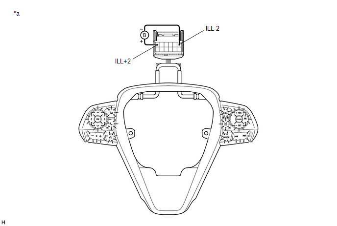
(b) Check the illumination.
|
*a | Component without harness connected
(Steering Pad Switch Assembly) |
- | - |
(1)
Connect a positive (+) lead from the auxiliary battery to terminal 1
(ILL+2) and a negative (-) lead to terminal 6 (ILL-2) of the steering
pad switch assembly connector.
(2) Check that the steering pad switch assembly illumination illuminates.
OK:
The steering pad switch assembly illumination illuminates.
HINT:
If the result is not as specified, replace the steering pad switch assembly.
Installation
INSTALLATION
PROCEDURE
1. INSTALL STEERING PAD SWITCH ASSEMBLY
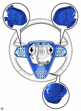
(a) Engage the 4 claws and 3 pins to install the steering pad switch assembly.
(b) Install the 2 screws.
(c) Connect the steering pad switch connector to the spiral cable with sensor sub-assembly.
2. INSTALL HORN BUTTON ASSEMBLY
Click here

Removal
REMOVAL
CAUTION / NOTICE / HINT
The
necessary procedures (adjustment, calibration, initialization or
registration) that must be performed after parts are removed and
installed, or replaced during steering pad switch assembly
removal/installation are shown below.
Necessary Procedures After Parts Removed/Installed/Replaced (for Gasoline Model) |
Replaced Part or Performed Procedure |
Necessary Procedure | Effect/Inoperative Function when Necessary Procedure not Performed |
Link |
|
*: When performing learning using the Techstream.
Click here  |
|
Disconnect cable from negative auxiliary battery terminal |
Perform steering sensor zero point calibration |
Lane Departure Alert System (w/ Steering Control) |
|
|
Pre-collision System |
|
Intelligent Clearance Sonar System* |
|
Lighting System (for Gasoline Model with Cornering Light) |
|
Memorize steering angle neutral point |
Parking Assist Monitor System |
|
|
Panoramic View Monitor System |
|
Necessary Procedures After Parts Removed/Installed/Replaced (for HV Model) |
Replaced Part or Performed Procedure |
Necessary Procedure | Effect/Inoperative Function when Necessary Procedure not Performed |
Link |
|
*: When performing learning using the Techstream.
Click here |
|
Disconnect cable from negative auxiliary battery terminal |
Perform steering sensor zero point calibration |
Lane Departure Alert System (w/ Steering Control) |
|
|
Pre-collision System |
|
Intelligent Clearance Sonar System* |
|
Lighting System (for HV Model with Cornering Light) |
|
Memorize steering angle neutral point |
Parking Assist Monitor System |
|
|
Panoramic View Monitor System |
|
PROCEDURE
1. REMOVE HORN BUTTON ASSEMBLY
Click here
2. REMOVE STEERING PAD SWITCH ASSEMBLY
(a) Disconnect the steering pad switch connector from the spiral cable with sensor sub-assembly.
(c) Disengage the 4 claws and 3 pins to remove the steering pad switch assembly.