Adjustment
ADJUSTMENT
PROCEDURE
1. STEERING WHEEL OFF CENTER ADJUSTMENT PROCEDURE
(a) Inspect steering wheel off center.
(1) Turn the steering wheel assembly to the center position.
| (2) Apply masking tape to the top center of the steering wheel assembly and upper steering column cover. |
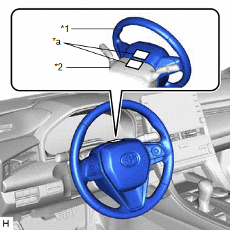 |
|
*1 | Steering Wheel Assembly | |
*2 | Upper Steering Column Cover | |
*a | Masking Tape | | |
(3)
Drive the vehicle in a straight line for 100 m (328 ft.) at a constant
speed of 56 km/h (35 mph), while holding the steering wheel assembly to
maintain the course.
| (4) Draw a line on the masking tape as shown in the illustration. |
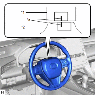 |
|
*1 | Upper Steering Column Cover | |
*2 | Steering Wheel Assembly | |
*a | Marked Line | | |
(5) Turn the steering wheel assembly to the center position.
| (6) Draw a new line on the masking tape on the steering wheel assembly as shown in the illustration. |
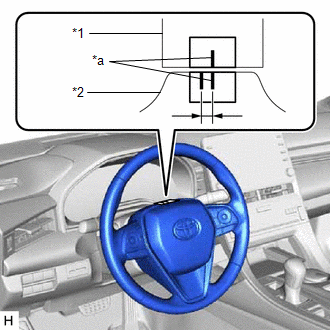 |
|
*1 | Upper Steering Column Cover | |
*2 | Steering Wheel Assembly | |
*a | Marked Line | | |
(7) Measure the distance between the 2 lines on the masking tape on the steering wheel assembly.
(8) Convert the measured distance to the steering angle.
HINT:
- Measured distance of 1 mm (0.0394 in.) = Steering angle of approximately 1 degree
- Make a note of the steering angle.
(b) Adjust the steering angle.
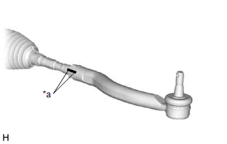
| (1) Put matchmarks on the tie rod assemblies LH and RH and steering rack end sub-assembly respectively. |
|
(2) Using a paper gauge, measure the thread length of the steering rack end sub-assemblies.
HINT:
- Measure both RH and LH sides.
- Make a note of the measured values.
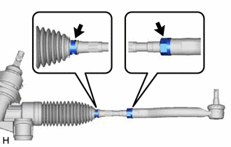
| (3) Remove the steering rack boot clips from the RH and LH steering rack boots. |
|
(4) Loosen the RH and LH lock nuts.
(5)
Turn the RH and LH steering rack end sub-assemblies by the same amount
(but in different directions) according to the measured steering angle.
HINT:
One
360 degree turn of a steering rack end sub-assembly (1.5 mm (0.0591
in.) horizontal movement) equals 9.2 degrees of steering angle.
(6) Tighten the RH and LH lock nuts to the specified torque.
Torque:
88 N·m {897 kgf·cm, 65 ft·lbf}
NOTICE:
Make
sure that the difference in thread length between the RH and LH
steering rack end sub-assemblies is within 1.5 mm (0.0591 in.).
(7) Install the RH and LH steering rack boot clips.
HINT:
Make sure that the tabs of the RH and LH steering rack boot clips are positioned within the area shown in the illustration.
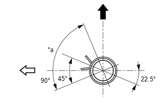
|
*a | Clip Tab Positioning Area |
 |
Up |
 |
Rear of Vehicle |
On-vehicle Inspection
ON-VEHICLE INSPECTION
PROCEDURE
1. INSPECT STEERING WHEEL FREE PLAY
(a) for Gasoline Model:
Start the engine and make sure that the vehicle is in a state in which the power steering can operate.
(b) for HV Model:
Turn the power switch on (READY) so that the power steering is ready to operate.
(c) Stop the vehicle and align the front wheels facing straight ahead.
(d) Gently turn the steering wheel right and left, and check for steering wheel free play.
Maximum Free Play:
30 mm (1.18 in.)
HINT:
If the free play exceeds the maximum, check the steering system.
Click here 
Precaution
PRECAUTION
HANDLING PRECAUTIONS FOR STEERING SYSTEM
(a)
Care must be taken when replacing parts. Incorrect replacement may
affect the performance of the steering system and result in a driving
hazard.
HANDLING PRECAUTIONS FOR SRS AIRBAG SYSTEM
(a)
This vehicle is equipped with a Supplemental Restraint System (SRS).
Failure to carry out service operations in the correct sequence could
cause the SRS to unexpectedly deploy during servicing. This may cause a
serious accident. Before servicing (including inspection, replacement,
removal, and installation of parts), be sure to read the precautionary
notices for Supplemental Restraint System.
for HV Model: Click here

for Gasoline Model: Click here

HANDLING PRECAUTIONS FOR STEERING COLUMN
(a) for Manual Tilt and Manual Telescopic Steering Column:
(1) Do not release the tilt lever when the steering column assembly is not installed on the vehicle.
HANDLING PRECAUTION FOR SPIRAL CABLE
(a)
Do not remove/install the spiral cable with sensor sub-assembly with
the auxiliary battery connected and the engine switch (for Gasoline
Model) or power switch (for HV Model) on (IG).
(b)
Do not rotate the spiral cable with sensor sub-assembly without the
steering wheel assembly installed, with the auxiliary battery connected
and the engine switch (for Gasoline Model) or power switch (for HV
Model) on (IG).
(c) Ensure that the steering wheel assembly is installed and aligned straight when inspecting the steering sensor.
(d)
Be sure that the spiral cable is in the center position during
installation and when removing and installing the steering wheel.
Click here

CAUTION:
If the steering wheel is turned without the spiral cable installed in the center position, the cable may break.
PRECAUTION WHEN REPLACING STEERING LOCK ACTUATOR ASSEMBLY
Before replacing the steering lock actuator assembly, refer to Registration.
for HV Model: Click here 
for Gasoline Model: Click here

Problem Symptoms Table
PROBLEM SYMPTOMS TABLE
HINT:
- Use the table below to help determine the cause of problem symptoms. If
multiple suspected areas are listed, the potential causes of the
symptoms are listed in order of probability in the "Suspected Area"
column of the table.
- Check each symptom by checking the suspected areas in the order they are listed. Replace parts as necessary.
- Inspect the fuses and relays related to this system before inspecting the suspected areas below.
Steering System |
Symptom | Suspected Area |
Link |
|
Heavy steering | Front tires (improperly inflated, unevenly worn) |
 |
|
Front wheel alignment (incorrect) |
 |
|
Front suspension (Lower ball joint) |
 |
|
Rack and pinion power steering gear assembly |
 *3 *3
 *4 *4 |
|
Steering column assembly |
 *1 *1
 *2 *2 |
|
Battery and power source circuit |
 *3 *3
 *4 *4 |
|
Power source voltage of power steering ECU |
 *3 *3
 *4 *4 |
|
Power steering ECU (Rack and pinion power steering gear assembly) |
 *3 *3
 *4 *4 |
|
Vehicle
condition (Steering wheel is turned from left to right repeatedly with
vehicle stopped or heavy load is continuously applied to vehicle) |
 *3 *3
 *4 *4 |
|
CAN communication system |
 *3 *3
 *4 *4 |
|
Steering effort differs between right and left or is uneven |
Power steering motor (Rack and pinion power steering gear assembly) |
 *3 *3
 *4 *4 |
|
Torque sensor zero point calibration |
 *3 *3
 *4 *4 |
|
Front tires (improperly inflated, unevenly worn) |
 |
|
Front wheel alignment (incorrect) |
 |
|
Front suspension (Lower ball joint) |
 |
|
Rack and pinion power steering gear assembly |
 *3 *3
 *4 *4 |
|
Steering column assembly |
 *1 *1
 *2 *2 |
|
Power steering ECU (Rack and pinion power steering gear assembly) |
 *3 *3
 *4 *4 |
|
While
driving, steering effort does not change in accordance with vehicle
speed, or steering wheel does not return to its centered position easily |
Power steering motor (Rack and pinion power steering gear assembly) |
 *3 *3
 *4 *4 |
|
Front tires (improperly inflated, unevenly worn) |
 |
|
Front wheel alignment (incorrect) |
 |
|
Combination meter assembly |
 |
|
Rack and pinion power steering gear assembly |
 *3 *3
 *4 *4 |
|
Steering column assembly |
 *1 *1
 *2 *2 |
|
Front suspension (Lower ball joint) |
 |
|
Skid control ECU (Brake actuator assembly) |
 *3 *3
 *4 *4 |
|
Speed sensor |
 *3 *3
 *4 *4 |
|
Torque sensor (Rack and pinion power steering gear assembly) |
 *3 *3
 *4 *4 |
|
Power steering ECU (Rack and pinion power steering gear assembly) |
 *3 *3
 *4 *4 |
|
CAN communication system |
 *3 *3
 *4 *4 |
|
Knocking or clunking sound occurs when turning steering wheel back and forth while power steering is in operation |
Rack and pinion power steering gear assembly |
 *3 *3
 *4 *4 |
|
Steering column assembly |
 *1 *1
 *2 *2 |
|
Steering intermediate shaft assembly |
 *1 *1
 *2 *2 |
|
Front suspension (Lower ball joint) |
 |
|
Friction sounds occur when turning steering wheel during low speed driving |
Power steering motor (Rack and pinion power steering gear assembly) |
 *3 *3
 *4 *4 |
|
Steering column assembly |
 *1 *1
 *2 *2 |
|
Spiral cable with sensor sub-assembly |
 |
|
Steering column cover contacting steering wheel assembly |
 *1 *1
 *2 *2 |
|
High-pitched sound (squeaking) occurs when turning steering wheel slowly with vehicle stopped |
Power steering motor (Rack and pinion power steering gear assembly) |
 *3 *3
 *4 *4 |
|
Steering wheel installation (incorrect) |
 |
|
Steering wheel vibrates and noise occurs when turning steering wheel from lock to lock |
Power steering motor (Rack and pinion power steering gear assembly) |
 *3 *3
 *4 *4 |
|
Steering column assembly |
 *1 *1
 *2 *2 |
|
Steering wheel installation (incorrect) |
 |
*1: for Manual Tilt and Manual Telescopic Steering Column
*2: for Power Tilt and Power Telescopic Steering Column
*3: for HV Model
*4: for Gasoline Model




 *3
*3 *4
*4 *1
*1 *2
*2 *3
*3 *4
*4 *3
*3 *4
*4 *3
*3 *4
*4 *3
*3 *4
*4 *3
*3 *4
*4 *3
*3 *4
*4 *3
*3 *4
*4


 *3
*3 *4
*4 *1
*1 *2
*2 *3
*3 *4
*4 *3
*3 *4
*4


 *3
*3 *4
*4 *1
*1 *2
*2
 *3
*3 *4
*4 *3
*3 *4
*4 *3
*3 *4
*4 *3
*3 *4
*4 *3
*3 *4
*4 *3
*3 *4
*4 *1
*1 *2
*2 *1
*1 *2
*2
 *3
*3 *4
*4 *1
*1 *2
*2
 *1
*1 *2
*2 *3
*3 *4
*4
 *3
*3 *4
*4 *1
*1 *2
*2