Components
COMPONENTS
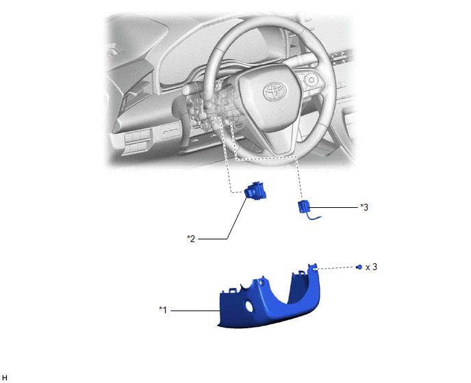
ILLUSTRATION
|
*1 | LOWER STEERING COLUMN COVER |
*2 | TILT AND TELESCOPIC SWITCH |
|
*3 | SPIRAL CABLE CONNECTOR |
- | - |
Inspection
INSPECTION
PROCEDURE
1. INSPECT TILT AND TELESCOPIC SWITCH
(a) Remove the tilt and telescopic switch.
Click here

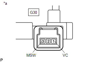
| (b) Measure the resistance according to the value(s) in the table below.
Standard Resistance: |
Tester Connection | Condition |
Specified Condition | |
G30-1 (VC) - G30-3 (MSW) |
Tilt up | 342 to 378 Ω | |
Tilt down | 1890.5 to 2089.5 Ω | |
Telescopic contract |
750.5 to 829.5 Ω | |
Telescopic extend |
152 to 168 Ω | If the result is not as specified, replace the tilt and telescopic switch. |
 |
|
*a | Component without harness connected
(Tilt and Telescopic Switch) | | |
Installation
INSTALLATION
PROCEDURE
1. INSTALL TILT AND TELESCOPIC SWITCH
(a) Engage the claw to install the tilt and telescopic switch.
(b) Connect the tilt and telescopic connector to the tilt and telescopic switch.
(c) Connect the spiral cable connector to the spiral cable sub-assembly.
2. CONNECT CABLE TO NEGATIVE AUXILIARY BATTERY TERMINAL
for Gasoline Model: Click here

for HV Model: Click here
NOTICE:
When disconnecting the cable, some systems need to be initialized after the cable is reconnected.
Click here
3. INSTALL LOWER STEERING COLUMN COVER
Click here
4. INSPECT SRS WARNING LIGHT
for Gasoline Model: Click here
for HV Model: Click here
5. CUSTOMIZE POWER TILT AND POWER TELESCOPIC STEERING COLUMN SYSTEM
Click here
Removal
REMOVAL
CAUTION / NOTICE / HINT
The
necessary procedures (adjustment, calibration, initialization or
registration) that must be performed after parts are removed and
installed, or replaced during tilt and telescopic switch
removal/installation are shown below.
Necessary Procedures After Parts Removed/Installed/Replaced (for Gasoline Model) |
Replaced Part or Performed Procedure |
Necessary Procedure | Effect/Inoperative Function when Necessary Procedure not Performed |
Link |
|
*: When performing learning using the Techstream.
Click here  |
|
Disconnect cable from negative auxiliary battery terminal |
Perform steering sensor zero point calibration |
Lane Departure Alert System (w/ Steering Control) |
|
|
Pre-collision System |
|
Intelligent Clearance Sonar System* |
|
Lighting System (for Gasoline Model with Cornering Light) |
|
Memorize steering angle neutral point |
Parking Assist Monitor System |
|
|
Panoramic View Monitor System |
|
Necessary Procedures After Parts Removed/Installed/Replaced (for HV Model) |
Replaced Part or Performed Procedure |
Necessary Procedure | Effect/Inoperative Function when Necessary Procedure not Performed |
Link |
|
*: When performing learning using the Techstream.
Click here |
|
Disconnect cable from negative auxiliary battery terminal |
Perform steering sensor zero point calibration |
Lane Departure Alert System (w/ Steering Control) |
|
|
Pre-collision System |
|
Intelligent Clearance Sonar System* |
|
Lighting System (for HV Model with Cornering Light) |
|
Memorize steering angle neutral point |
Parking Assist Monitor System |
|
|
Panoramic View Monitor System |
|
PROCEDURE
1. CHANGE POWER TILT AND POWER TELESCOPIC STEERING COLUMN SYSTEM SETTINGS
Click here
2. REMOVE LOWER STEERING COLUMN COVER
Click here
3. DISCONNECT CABLE FROM NEGATIVE AUXILIARY BATTERY TERMINAL
for Gasoline Model: Click here
for HV Model: Click here
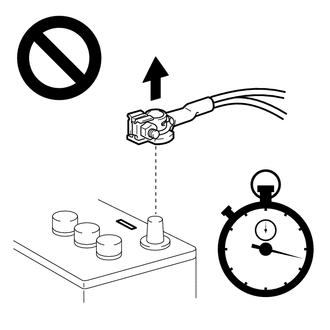
CAUTION:
Wait
at least 90 seconds after disconnecting the cable from the negative (-)
auxiliary battery terminal to disable the SRS system.
NOTICE:
When disconnecting the cable, some systems need to be initialized after the cable is reconnected.
Click here
4. REMOVE TILT AND TELESCOPIC SWITCH
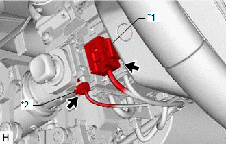
| (a) Disconnect the spiral cable connector from the spiral cable sub-assembly. |
 |
|
*1 | Spiral Cable Connector | |
*2 | Tilt and Telescopic Connector | | |
(b) Disconnect the tilt and telescopic connector from the tilt and telescopic switch.
(c) Disengage the claw and pull out the tilt and telescopic switch.
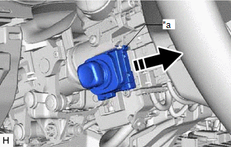
|
*a | Claw |
 |
Pull out in this direction |


